

How to Read a Component Datasheet — A Step-by-Step Guide for Engineers

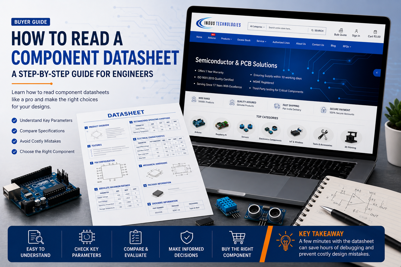
How to Read a Component Datasheet — A Step-by-Step Guide for Engineers
Every reliable electronic design begins with one document engineers often skim past too quickly: the component datasheet. Whether you're a student building your first embedded project or a junior engineer finalizing a Bill of Materials (BOM), knowing how to read a component datasheet is one of the most valuable skills you can develop. A datasheet tells you everything about how a part behaves — its limits, its ideal operating conditions, and how it should be connected — long before you ever power it on.
In this guide, we'll break down every major section of a typical electronic component datasheet, explain what each one means in practical terms, and walk through a real example using the Arduino UNO Q — a hybrid Linux + real-time development board available at Indus Technologies — so you can see the process applied to an actual product rather than a theoretical one.
Table of Contents
- What is a Component Datasheet?
- Why Reading a Datasheet is Important
- Key Sections of a Datasheet
- Step-by-Step Guide to Reading a Datasheet
- Practical Example: Arduino UNO Q
- Common Mistakes to Avoid
- Best Practices
- Conclusion
- Frequently Asked Questions
What is a Component Datasheet?
A component datasheet is the official technical document published by a manufacturer that describes exactly how a part behaves, how it should be used, and under what conditions it performs safely. It covers everything from basic functionality to precise electrical limits, pin layouts, package dimensions, and ordering codes.
Think of it as the instruction manual and specification sheet combined into one document. For any electronic component datasheet — whether it's a resistor, a microcontroller, or a full single-board computer — the datasheet is the single source of truth an engineer should rely on before adding a part to a design.
Why Reading a Datasheet is Important
Skipping the datasheet is one of the most common causes of design rework. A component might look right based on its name or category, but only the datasheet confirms whether it will actually work in your circuit.
- Prevents design errors: Confirms voltage, current, and signal compatibility before the part reaches your PCB.
- Avoids costly respins: A missed pin mapping or footprint mismatch can mean an entire board revision.
- Improves reliability: Operating within recommended conditions — not just maximum ratings — extends product lifespan.
- Speeds up component selection: A five-minute datasheet review can eliminate an unsuitable part before it ever enters your BOM.
Key Sections of a Datasheet
Datasheet formats vary slightly between manufacturers, but nearly every one of them follows a similar structure. Here's what each section tells you and why it matters.
| Datasheet Section | Why It Matters |
|---|---|
| Product Description / Overview | Gives a quick summary of what the part is and whether it fits your general use case. |
| Key Features | Highlights standout capabilities — power modes, interfaces, or performance figures. |
| Pin Configuration / Pinout | Defines every physical connection point, essential for PCB and wiring design. |
| Absolute Maximum Ratings | Defines the survival limits of the device — never a target operating point. |
| Recommended Operating Conditions | The safe, reliable range in which the component should actually be used. |
| Electrical Characteristics | Detailed performance parameters such as current draw, timing, and voltage behavior. |
| Mechanical / Package Information | Physical dimensions, footprint, and mounting details needed for PCB layout. |
| Ordering Information | Confirms the exact part number, variant, and packaging to order — avoiding costly mix-ups. |
Step-by-Step Guide to Reading a Datasheet
Follow this sequence any time you evaluate a new component — it mirrors how experienced engineers actually work through a datasheet before adding a part to a design.
- Read the product overview first. This tells you in seconds whether the part is even in the right category for your project.
- Check the supply voltage / power requirements. Compare your system's supply against the component's operating range.
- Review the pin configuration. Confirm pin count, function, orientation, and package type before layout begins.
- Study the electrical characteristics table. This defines real-world performance — not just what's theoretically possible.
- Note the absolute maximum ratings. Treat these as hard limits your design should never approach in normal operation.
- Confirm the recommended operating conditions. This is the range your design should actually target for reliability.
- Check mechanical and package details. Verify the footprint matches your PCB or enclosure plans.
- Verify ordering information. Double-check the exact part number, variant, and packaging before placing an order.
Practical Example: Reading the Arduino UNO Q Datasheet
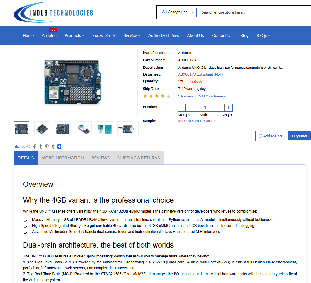
Theory is useful, but datasheets make far more sense once you apply them to a real product. Let's walk through the process using the Arduino UNO Q, a hybrid Linux + real-time development board available at Indus Technologies, and one of the most talked-about boards in the current Arduino ecosystem.
5.1 Product Overview
The Arduino UNO Q is a single-board computer built around a dual-processor "split-brain" architecture: a Qualcomm Dragonwing QRB2210 microprocessor (MPU) running a full Linux/Debian environment, paired with an STM32U585 microcontroller (MCU) for real-time hardware control. This combination is why the board is aimed at Edge AI, computer vision, robotics, and IoT applications rather than simple sketch-based projects alone.
Why engineers check this: The overview instantly tells you whether the board suits your project category — in this case, applications that need both Linux-level computing and deterministic, real-time I/O on a single board. Skipping this step risks selecting a board that is either overpowered or underpowered for your actual requirement.
5.2 Key Features
- Qualcomm Dragonwing QRB2210 MPU — quad-core Arm Cortex-A53 at 2.0 GHz with Adreno GPU
- STM32U585 MCU — Arm Cortex-M33 running Arduino sketches on Zephyr OS for real-time control
- LPDDR4 RAM (2 GB / 4 GB variants) with 16 GB / 32 GB eMMC onboard storage
- Dual-band Wi-Fi and Bluetooth for wireless connectivity
- USB-C connector supporting power delivery and video output
- Classic Arduino UNO header footprint plus a Qwiic connector for quick sensor expansion
Why engineers check this: The features list narrows down whether the board's connectivity and compute resources actually match your project scope — for example, whether onboard Wi-Fi eliminates the need for an external module.
5.3 Pin Configuration
The UNO Q retains the familiar Arduino UNO header layout — digital and analog I/O pins, power rails, and communication interfaces — while adding a Qwiic connector for I2C-based sensor expansion and a high-density bottom header for MPU-side peripherals such as camera and display interfaces.
Why engineers check this: Because the board maintains UNO-compatible headers, most existing shields are expected to fit — but engineers should still verify pin function and voltage levels before reusing shields designed for older, 5V-only Arduino boards, since some UNO Q I/O operates at 3.3V logic.
5.4 Absolute Maximum Ratings
This section defines the survival limits of the board — power input range, storage temperature, and maximum voltage tolerances on I/O pins. Exceeding these values, even briefly, can cause permanent damage to the MPU or MCU.
Why engineers check this: These figures exist to protect the hardware, not to guide normal operation. A junior engineer designing a power supply circuit around these numbers — instead of the recommended operating range below — risks unreliable, short-lived hardware.
5.5 Recommended Operating Conditions
| Parameter | Typical Recommended Range |
|---|---|
| Power Input (USB-C) | 5V regulated supply |
| I/O Logic Level | 3.3V (verify per-pin before interfacing with 5V shields) |
| Operating Temperature | Standard commercial range (check exact figures in the manufacturer datasheet) |
| Wireless Connectivity | Dual-band Wi-Fi and Bluetooth, active during normal operation |
Why engineers check this: Designing within the recommended range — rather than the absolute maximum — is what keeps a board like the UNO Q running reliably across long project lifecycles, especially in always-on IoT or robotics deployments.
5.6 Electrical Characteristics
The electrical characteristics section documents detailed behavior such as current draw under different processing loads, USB-C power delivery negotiation, and I/O drive strength. For a dual-processor board like the UNO Q, this is where you'd confirm how power consumption changes between idle, Linux-active, and full AI-inference workloads.
Why engineers check this: If you're powering the board from a battery or a constrained power budget — common in robotics and portable IoT devices — these figures determine whether your power system can sustain peak MPU load without brownouts.
5.7 Mechanical Dimensions
The UNO Q keeps the classic Arduino UNO board outline and mounting hole positions, making it compatible with existing UNO-format enclosures, standoffs, and shield stacks.
Why engineers check this: Confirming mechanical dimensions early avoids enclosure redesigns late in the project — particularly important when integrating the board into an existing product housing.
5.8 Package Information
As a fully assembled single-board computer rather than a discrete IC, the UNO Q's "package information" refers to the board assembly itself — connector placement, header spacing, and antenna positioning for the onboard wireless module.
Why engineers check this: Antenna and connector placement affects enclosure design and signal performance — details easy to overlook if you only skim the feature list.
5.9 Ordering Information
The Arduino UNO Q is available in two memory variants — a 2 GB RAM / 16 GB eMMC model and a 4 GB RAM / 32 GB eMMC model. Confirming the exact variant, manufacturer part number, and packaging before ordering prevents receiving a board with insufficient memory for your intended workload.
Why engineers check this: Choosing the wrong RAM/storage variant for an AI-inference or multi-camera project can mean the board technically works but performs far below expectations — an expensive mistake to discover after deployment.
What Did We Learn from This Example?
✔ Does the board match the project's compute and I/O requirements?
✔ Are the logic voltage levels compatible with existing shields and sensors?
✔ Which RAM/storage variant fits the intended workload?
✔ What are the power and thermal limits under real operating conditions?
✔ Does the mechanical footprint fit the intended enclosure?
Common Mistakes to Avoid
| Mistake | Consequence |
|---|---|
| Treating absolute maximum ratings as design targets | Reduced reliability, premature failure in the field |
| Ignoring logic voltage levels between old and new boards | Damaged I/O pins or malfunctioning shields |
| Skipping the ordering information section | Wrong variant, package, or memory configuration ordered |
| Relying on an outdated datasheet revision | Missed errata or changed specifications |
| Assuming footprint compatibility without checking mechanical drawings | Enclosure or PCB layout rework |
Best Practices
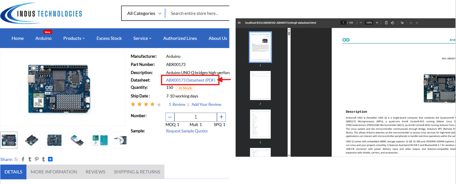
- Always download the datasheet directly from the manufacturer's official page to ensure you have the latest revision.
- Keep a personal checklist (supply voltage, pinout, ratings, package, ordering code) and run through it for every new component.
- Design around recommended operating conditions, with margin — not around absolute maximum ratings.
- Cross-check mechanical dimensions against your enclosure or PCB footprint before finalizing layout.
- When in doubt about a parameter, contact the supplier's technical team rather than guessing.
Conclusion
Learning how to read a component datasheet is a foundational engineering skill that pays off on every project you touch — from a simple resistor to a hybrid single-board computer like the Arduino UNO Q. The process is always the same: understand the overview, verify voltage and pin compatibility, respect maximum ratings, design within recommended conditions, and confirm the exact ordering details before you buy.
Make this a habit early in your engineering journey, and you'll avoid the majority of design errors, mismatched components, and costly PCB revisions that catch beginners off guard.
Find the Right Components at Indus Technologies
From the Arduino UNO Q to passive components, sensors, and power devices, explore genuine parts with detailed specifications to help you make confident engineering decisions.
Browse Arduino Boards Submit Bulk QuoteFrequently Asked Questions
Q1: What is a component datasheet?
A component datasheet is the manufacturer's official technical document describing a part's specifications, electrical behavior, pinout, mechanical dimensions, and ordering details.
Q2: Why should engineers read datasheets before selecting a component?
Datasheets confirm whether a component actually fits the application's voltage, current, and mechanical requirements — preventing design errors, wrong orders, and costly PCB revisions later in the project.
Q3: Which datasheet parameters are most important?
Supply voltage range, absolute maximum ratings, recommended operating conditions, and pin configuration are typically the most critical for initial component evaluation.
Q4: How do datasheets help during PCB design?
They provide exact pin functions, package dimensions, and footprint data needed to lay out a board correctly, reducing the risk of mismatched footprints or incorrect pin assumptions.
Q5: Where can I find genuine component datasheets?
Always source datasheets from the original manufacturer's website (such as Texas Instruments, STMicroelectronics, or Arduino's official documentation) or from an authorized distributor like Indus Technologies to ensure the information is accurate and current.
References
- Arduino Official Documentation — UNO Q Hardware Reference
- Texas Instruments — Component Datasheet Standards
- STMicroelectronics — STM32U585 Reference Documentation
- IPC Standards — Component and PCB Design Guidelines
-

-

November 27, 2025
Connecting the Dots: How Electronic Components Work Together in Devices -

November 27, 2025
How reliable is your electronics components supplier